
The tutorial describes how to create the Sea Hawk in virtual reality but the dimensions and procedure are similar for making the craft in the real world.
If you want to see photos of builds at our three partner schools, scroll all the way down!
Using Blender:
In the Scene Panel set Units to Metric (we will use Metric throughout this program and try to avoid the kind of conversion problems that led to a Mars probe completely missing the red planet!). Click on the "Separate" toggle. A good tutorial for this setup is here: http://www.katsbits.com/tutorials/blender/metric-imperial-units.php#gridspacing
Start by changing your grid size to 1000 lines at a scale of .005 by going to View>Properties (or use the N key to call up the Properties panel) and underneath "Grid Floor" set Lines:1000, Scale .005. In this way we create a 5 meter by 5 meter grid in which each of the smallest squares in the grid is .5 cm (half a cm) which should be sufficient for our purposes.
Add a plane (Shift-A, add plane) and make its dimensions (using the Dimensions tab in the Properties window (N) X:1m and Y:1m and Z:0m. This represents the basic sheet of plastic one might use (we will add the Z dimension later).
Now move the plane into the top right quadrant by hitting "g" (for grab) then "x" (to lock in the x direction) and then ".5" (to move the cube 50 cm to the right) and hit enter. Then hit "g" again, then "y" (for locking the y direction) then ".5" and enter and your plane should be in the top right quadrant.
Now, because the plastic sheets we use to build the Sea Hawk skin come in dimensions of 36 inches by 24 inches, we need to convert inches to cms and then cut our 1 meter squared sheet accordingly. 36 inches = 91.44 cm and 24 inches = 60.96 cm. We will round this to 92 cm and 61 cm accordingly.
To cut the 1 square meter sheet, go into Edit mode (hit Tab) and use the Loop Cut and Slide Tool under Mesh Tools (usually on the left side of the screen). Click on the top part of the square and move the purple line that appears along the x axis to the right until it shows 0.84. That should be 92 cm because the entire square has 100 units on the left side and 100 on the right side (each tiny square being half a cm) so you want 184 tiny squares to equal 92 cm.
Similarly, to cut the 1 square meter piece to 61 cm in the y direction, use the Loop Cut and Slide Tool and, clicking on the left edge of the square, move the line down from zero (the middle) to .22. This equals 122 little squares which repesents 61 cm. It should look like this:

Now select the extraneous faces using the edge and face select vertices toggles and delete them leaving the plane looking like the sheet of plastic we use for our Sea Hawk skin. Save the file under "SeaHawkPlasticSheet".

This is the basic sheet we will start with.
We must now cut it again, this time to the size we use for the Sea Hawk skin first layer.
The Sea Hawk dimensions are 30 inches by 20 inches, which translates to 76.2 cm and 50.8 cm respectively. We will round to 76 and 51 centimeters.
Start by moving the template down into the top right quadrant so that its left bottom corner is at the origin.
Use Loop Cut and Slide again, clicking on the top of the rectangle and move it over to 152 units (corresponding to 76 cm). Then do the same thing clicking on the left side and move the new edge to 102 units (corresponding to 51 cm).

Then select the faces you want to cut and remove them:
.png)
Once again move this new figure to the origin.
Now rotate the sheet by 90 degrees counter clockwise, align with the bottom left vertex to the origin and save as "SeaHawkSheet1".

Now we need to cut out the square where the Sea Perch fits into the Sea Hawk. We use the loop cut and slide tool to go up 13 inches (33 cm) and in 5 inches (12.7 cm, rounded to 12.5 cm) on either side. With our grid this means 66 units up from the origin and 25 units in from the origin on one side (along x) and 25 units in from the outer right edge on the other side:

Select the face you want to cut out (the bottom center face) and delete it:

Now select the top inner box, hit "w" for subdivide and you should end up with the following sequence of events:


Now select the lower left and top right vertices of the left top inner rectangle and hit "f" for face; this will create the horizontal triangle line. Do the same thing for the lower right and top left vertices fof the right top inner triangle and you should get this:

Sometimes it is difficult to get the faces to form correctly. When this happens it usually indicates that you may have double points or no points in the appropriate place at all. I click on the two end points of each line and click on subdivide and then select the overlapping points I've created, click "Merge" and then "remove duplicates". Then you should have faces such as seen below:

Once you have the correct geometry, select the right triangles on either side of the bow's isosceles triangle and use Mesh>Vertices>Separate>Part.

Once the parts are separated, tab from edit mode to object mode and place the right triangles on separate layers so you can rotate them. In the real world you would use your exacto knife (box cutter) on the lowest setting and simply perforate the plastic so you can fold them down to form the "beak" of the Sea Hawk.
In Edit mode, select all the faces of one piece of the boat the body of the boat for example) and tab into object mode and extrude in the Z axis .004 (this will give you the 4mm that the real plastic sheet has). Do this for each of the other pieces (the the two side right triangles). You will have to select the faces in edit mode, then toggle to object to do the extrusion. when you select them in Object mode, you should go to a side view and hit E for extrusion, then type in the .004 to get your millimeters.
To do the rotation of the front right triangles you will have to go into Edit mode and select the tip vertex of one of the triangles (at the base of the right angle at one of the top corners of the boat) and then go into Object mode and select Object>Transform>Origin to 3D cursor. Now that becomes your pivot point. (When you want to rotate the other triangle you will have to do the same procedure for the other side).

In one of your split windows (assuming you split your windows as I did, which you do by right clicking at the top of the window where it joins the menu bar and selecting "split area") go to the appropriate side view (I hit the 3 key, you might have to hit the 1 key, depending on which side you are working on) so that you have a YZ orthogonal view (if it is in perspective view you can switch through View>Perspec/Orthogonal or hit the 5 key toggle).
You will have to use multiple views to keep adjusting the angles of rotation until you get the right triangles where you want them, but in time you should be able to fold them down as shown in the picture below. In the real world craft it is a lot easier; you just fold them into place. But in Blender, once you have them where you want them, select each right triangle (i.e. the beak of the hawk) and THEN select the surface of the boat and click "ctl P" to parent them. The parent is always the active object which is the last object selected. Now you can move the boat around by the surface sheet, but can still move and adjust the beak parts which are the children.

Your angles will be something like X = -125, Y = -54 and Z = 89 for the port side, and X = -125, Y = 54 and Z = -89 for the starboard side.
Now move the boat to the grid by setting the Z location to 0 and align its left side to the y axis so you can start working on the wings.
This is a good time to save your work!
Now go to File>Append and select your "SeaHawkPlasticSheet" Plane. Align it so that the Sea Hawk model you just made is in the middle.

Move it to its own layer (command M) but make all layers visible.
Deselect everything in object mode and then select just the Plastic sheet plane.
Tab into Edit mode.
Use Loop Cut and Divide again to cut up the plane, but this time you can use your SeaHawk boat as a template, just as you would in the real world (using a sharpee instead of the Loop Cut and Divide tool!).

Select the face that corresponds to the Sea Perch docking hole and hit X and delete the face:

Now comes a slightly tricky part: You go to line mode (the center one of the three cubes on the menu) and select the vetical line running through the nose of the craft and subdivide, then click on the horizontal line in the middle and subdivide that, and do this for both sides. Then go into vertex mode (by clicking on the leftmost of the three cubes on the bottom menu after the 3D manipulators and the word "Global") and select the vertex on the square closest to the nose of the craft,and move it up so that it lines up with the triangular side of the craft underneath.

The picture above shows working on the port side of the craft, the starboard has already been done).

You may have to merge some points and remove doubles, but eventually you should be able to toggle into face mode and see something like this and select the faces you want to remove.

Now we can work on the wings. You want to measure up each of the wing edges 5 and 5/8 inches (5.625 inches) which is 14.3 cm for the top edge of the wing, and 3 and 3/8 inches (3.375 inches) which is 8.6 cm for the bottom edge of the wing. In the real world you then draw lines from these points to the points at the base of the isosceles triangle that forms the nose of the craft and cut along those lines. In Blender we will make the top edge 14.5 cm (29 units in Blender) and 8.5 cm for the bottom edge (17 units in our setup in Blender) and simply select the vertices of the squares and drag them into position.

(To mark those locations you could use the grease pencil (see http://wiki.blender.org/index.php/Doc:2.6/Manual/3D_interaction/Sketching/Drawing). You turn it on in the Tool Shelf (View>Toolshelf or hit T) and click New Layer and select a color. To use it, hold the D key down and the left mouse button. The problem with the grease pencil is that if you move your image in the layer beneath, you mark you made doesn't do with it, so choose the size you are going to work in and stick with it. I ultimately decided not to bother using it, but leave this in here for the adventurous who want another technique at their disposal.)
Now we want to extrude this sheet 4mm in Z so it has some dimension, and place it on top of the hull we made earlier.
Hit A to select all and hit 1 to go to the front ortho view.
Then hit E and type in .004 and hit return. Tab into Object mode and move the new wing surface into position and then make it the parent of the hull surface beneath (select the hull surface THEN shift right click the wing surface, then hit ctl P. If you make a mistake in the order and need to unparent, select the objects and hit Alt-P an clear).

Voila, you now have the Sea Hawk Skin completed! You can now add color and texture as you see fit (school colors perhaps?)

If you want to learn how to create the endoskeleton click here!
Meanwhile, in the Real World:
Now as for building the Sea Hawk in the real world, here are some photos:

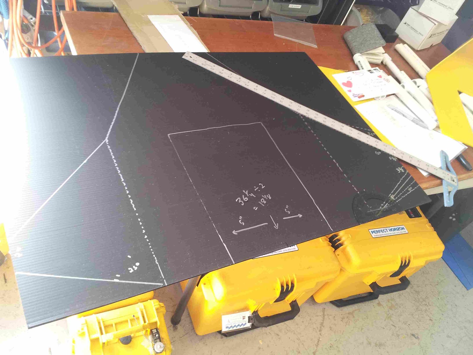
1. Start with the standard 4mm plastic sheet, 24 x 36 inches. Mark it at 20 x 30.

2. In the 20 x 30 inch section, draw a line parallel to the 20 inch side that is 13 inches in from what will be the stern of the boat, along the 30 inch long side. Draw two lines parallel to the 30 inch long side, measuring 5 inches in from each side. Mark a point midway at what will be the bow of the sheet (half way down the 20 inch side) and create an isosceles triangle by drawing down to the edges of the line you drew 13 inches in. You can also make another internal isosceles triangle as shown, but this is optional.

3. Cut away the excess 6 and 4 inches as shown above, using an exacto knife (box cutter).


5. Hold the Sea Hawk beak together by punching a hole through the bottom of the beak and tying with a twisty or zip tie.

6. Place the Sea Hawk beak surface upside down on another 36 x 24 inch sheet of 4mm plastic (use another color if it suits you; we try to use school colors!). Place it directly in the middle, by marking it at 18 inches and then measuring 5 inches out from the center, drawing lines and then placing the Hawk's beak surface (the yellow piece) so it lines up. On the wing surface (the black piece of plastic) draw lines around the entire Sea Hawk beak surface (like the police do with chalk lines around a dead body at the scene of a crime!).

7. Now take the Beak surface off leaving the wing surface sheet on your table.
You can now measure a top angle of 15 degrees off the line you drew representing the edge of the isosceles triangle with a compass to draw out the top part of the Sea Hawk's wing...

8. And a bottom angle of 25 degrees for the bottom part of the Sea Hawk's wing... or you can experiment with any angles you want (as you can see below, I tried several, but found the 15 degree/25 degree combo aesthetically sexiest!).

9. Or, alternatively, you can simply make a mark 3 3/8 inch from the bottom and another 5 5/8 inch off the bottom and connect the lines to as shown in the picture below. That way you don't need a compass (we used to all carry them in our school kit with pencils and crayons in elementary school, but try finding one in a high school today...!).
Because this is the same material we used in the Sea Perch to tie things together and the Sea Hawk evolved from the Sea Perch. Evolution is conservative. It tends to recycle old parts and materials. So in biomimicry terms, the Sea Hawk uses a mutated version of the Sea Perch DNA to create creature that can climb out of the ocean...

11. Now you have the Sea Hawk "skin" that will go on the Sea Hawk endoskeleton (which also "evolved" from the Sea Perch PVC endoskeleton!).
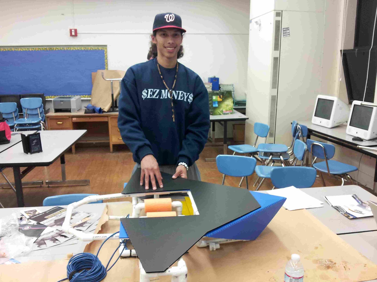
WASHINGTON PREPARATORY HIGH SCHOOL ROBOTICS CLUB:


Then EZ starts cutting, showing how... EZ it is to make one....


EZ and Luis lay out the PVC materials needed for two Sea Hawk's (each Sea Hawk needs 7 two foot sections of 1/2" PVC and the parts shown to their right)...


... and then they assemble one of the Sea Hawk frames...

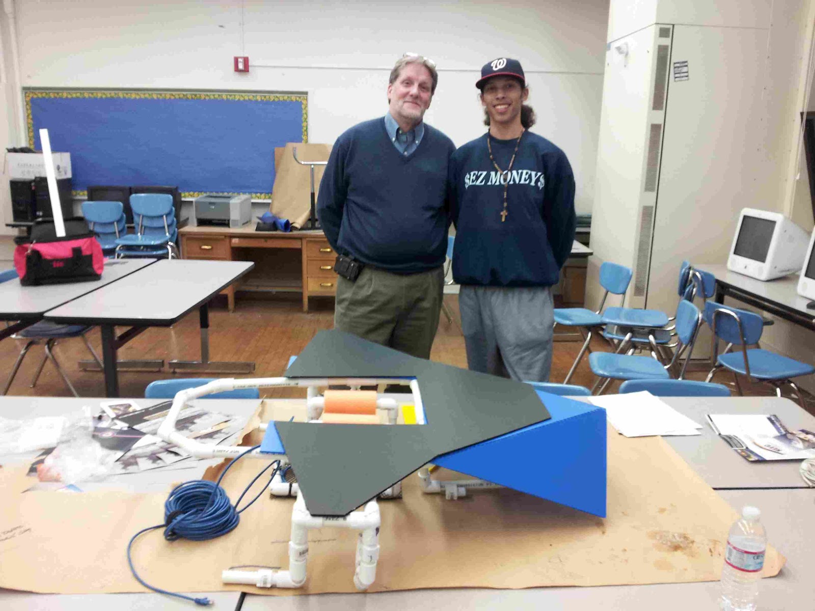
... and then EZ mounts the skin on the endo-skeleton and places the Sea Perch in its "docking bay"

Later that afternoon, New York based environmental technology consultant Kendall Christiansen from Insinkerator (the company that makes what you call "garbage disposals" and which we call "biofuel feedstock preparation devices) visits the school to see about our renewable energy initiative there and easy shows him the Sea Perch "sitting in the dock of the bay" and they discuss ways of powering oceanic human driven water craft and robo-boats using kitchen waste... noting that every navy ship and aircraft carrier has a huge amount of canteen waste they must deal with at sea -- a unique source of energy to generate electricity if ground up and fermented rather than dumped at sea!
Meanwhile, back at the shop, Motion Picture Marine's David Grober explores inexpensive plastic boxes that can be used to house the Arduino microcontrollers and motor shields that we will add to the craft...


The aesthetics aren't great yet... but we figure it has to be something cheap and available to stay in range of school budgets... the aesthetics will come!
VENICE HIGH SCHOOL ROBOTICS CLUB:


Now the Venice Sea Hawk is ready for its endoskeleton and then... on to motors and sensors!
WASHINGTON MATH SCIENCE TECHNOLOGY PUBLIC CHARTER SCHOOL (WMST) IN DC:

Above, the WMST team celebrating a dog and pony build out of the Sea Hawk/Sea Perch combo.
 |
| An early version of the Sea Sparrow (with clipped wings and single water bottle floats and a docked Sea Perch), with a Quadcopter that Evan Epic Polk successfully landed on the bow. |
 |
| The Sea Perch docked in the Sea Sparrow has the Spencer motor mount modification he developed for the Sea Hawk wherein the motors can be detached quickly for easy replacement; the concept is discussed in our "pimp your perch" blog post. |
 |
| This Sea Hawk (Sea Sparrow?) has no motors of its own and actually uses the docked Sea Perch as its source of propulsion. We use it as a mobile landing platform for ROV helicopters and quadracopters, an idea the ROTC students came up with to make their robots like the marines, capable of providing security for "land, sky and sea." |
 |
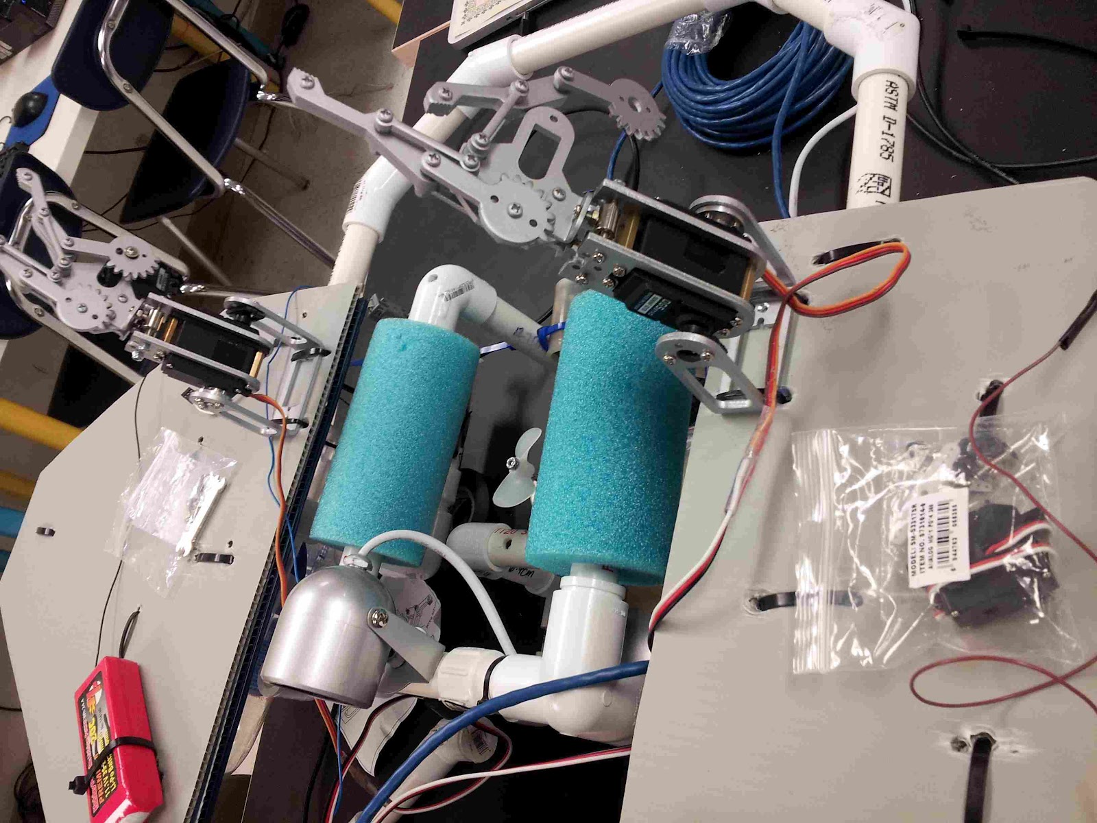
| The Sea Hawk/Sea Perch deck, all decked out with true functionality (but no waterproofing!). Here you can see the red 11.1 V LiPo batteries that power the Motor Shields (one for the Adafruit 4 motor shield that powers the 3 Sea Perch motors (each drawing .6 amp continuous and 1.2 amp peak) , and one for the DFRobot 2 Amp motor shield that powers the Sea Hawk motors (each drawing 1.2 amp continuous and 2 Amp peak with a 2 Amp fuse). You can also see the two Sparkfun Robotic claws on servos which will hold the Sea Perch in place by its blue floats. You can see the 8 pin telephone junction box that connects the Sea Perch ethernet cable to the Adafruit Motor shield (the left motor in M1, the right motor in M3 and the up/down motor in M2). And you can see the Arduino boards with their motor shields (the blue in front is the Adafruit controlling the Sea Perch and controlling the two robotic claws via servos connected to the red mini-breadboard shown, the green on the bottom is the arduino/DFRobot motorshield sandwhich controlling the Sea Hawk motors. At the bow of the boat you can see a breadboard with an Ultrasonic Ping sensor and a PIR sensor for some autonomy, connected to the Arduino board under the DF Robot Motor Shield so that the Sea Hawk can autonomously avoid walls and objects. Not shown are the two 9.6 volt batteries needed, one to power each Arduino). |
 |
| Here are the PIR sensor and Ultrasonic ping Sensor and a PAL Color sensor at the Stern of the boat, above the Sea Hawk beak. |
 |
| Here the PIR Motion Sensor, PING ultrasonic sensor and PAL color sensor being tested with the Sea Perch motors via the Adafruit Shield/Arduino Uno combo (normally we would use them with the Sea Hawk but we wanted to try them out with the Sea Perch) |

 |
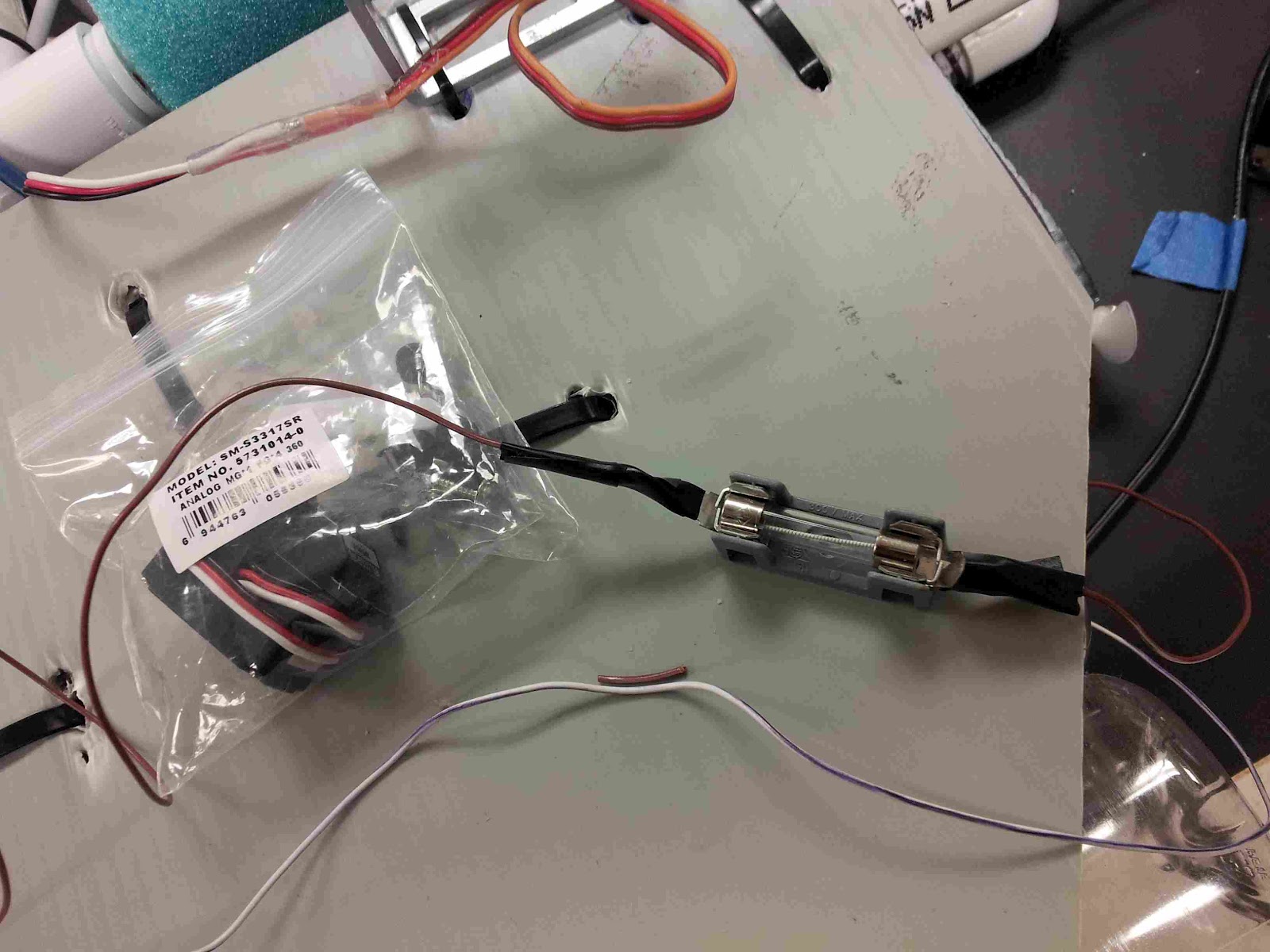
| Here is a makeshift fused on-off switch with indicator light connecting the 11.1 Volt LiPo battery (red) to the Motor Shield. |
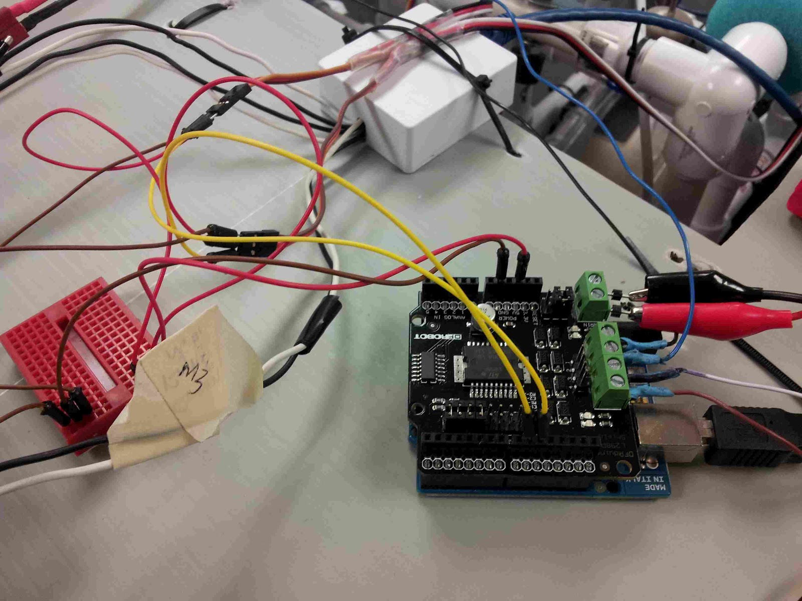 |
| This is the DFRobot 2A motor controller, running off of a red 11.1 V LiPo battery to control the Sea Hawk. The red mini-breadboard is used to connect the sensors and the servos, serving as an easy to to experiment with interface for plugging in different configurations. |
 |
| Another view of the 2A DFRobot Motor Shield on top of the Arduino that, together, control the Sea Hawk motors. Note that the Arduino must be powered separately from a 9.6 Volt NiMH or LiPo or NiCad hobby battery supply (don't use a typical 9 volt battery as they don't last long enough to do any robotics work and you will be hauling your boat in long before the competition is over to replace the battery -- use a hobby battery with enough amperage to last an hour!) The 9.6 v source for the Arduino is not shown here but you can see the 11.1 V battery that powers the Motor Shield -- it is crucial to have a SEPARATE battery source for the motors and for the Arduino! Watch your jumper settings to make sure you connect things correctly. |

 |
| The Sea Perch here has an IR/RGB video camera mounted on its bow for real-time underwater videography; with this, when the students pilot the Sea Perch using signals sent from their computer keyboard (using the Arduino Serial monitor) via Xbee Explorer to the Xbee Receiver which will be mounted on the Arduino/Adafruit sandwhich, they won't have to "'peer into the pool' to pilot their Perch", they will pilot it remotely wherever it is deployed. |
 |
| Here you can see an otter box (clear plastic case) with the MIT Sea Perch Sensor suite mounted inside and placed on the mat of the Sea Perch. The MIT Sea Perch Sensor Suite enables the Sea Perch to gather data on temperature, salinity, depth (pressure) and turbidity (light) and stores it with a clock stamp on an SD card to be uploaded upon retrieval to Google Digital Ocean. |
 |
| The Sea Hawk enables the Sea Perch to leave the shore. The Sea Perch is now tethered to the white junction box on the boat (center of picture) which connects to the Arduino-MotorShield-Xbee sandwhich. The Sea Hawk boat, using its servo controlled robotic claws, can take the Sea Perch anywhere! |
 |
| Mr. Nouristani put 2 Amp uses between the positive wire of each motor and the DFRobot motor shield because experiments with the ammeter showed that if the 1.2 Amp motors get stuck (for example in Sea Weed) they can draw up to 5 amps, which would burn out the chips. |
 |
| WMST Robotics Club instructor Mohammed Nouristani engages in a deep thought experiment to figure out how we are going to water-proof all these messy electronics! |
 |
| The Sea Hawk flotation is achieved by a cluster of six 1 liter water bottles in the beak of the craft and two 3 bottle clusters of 1.5 liter water bottles under each wing of the craft. In this way the Sea Hawk takes the plastic water bottle trash problem "under its wing" and PORPOISE helps re-purpose the oceanic trash into useful items for environmental sensing. In this picture you can also see the motors mounted on the Sea Hawk, and note that they appear identical to the Sea Perch motors except for the way they are mounted (we don't use zip ties anymore, we use T's). The only difference between the Sea Hawk and Sea Perch motors from a functional standpoint is that the Sea Hawk motors are twice as powerful (1.2 Amps continuous versus 0.6 amps). As such they need more powerful motor controllers and fuses. |
In the video above, Culhane explains the Sea Perch/Sea Hawk concept at WMST.
In the video above EZ Money and Juhayra explain the Sea Perch/Sea Hawk concept at Washington Prep.
No comments:
Post a Comment